Successful cooperation with Brugg Cables to ensure permanent temperature monitoring of power cables connected to the construction of the 2008 Olympic City in Beijing.
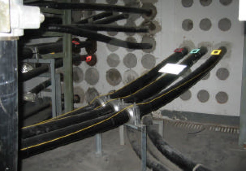 With more than a hundred high voltage orders received in China up to now, Brugg Cables is a reliable supplier for customized cable system solutions. This was the main reason for the Capital’s utility Beijing Electric Power Corporation to select Brugg Cables in 2005 as the supplier for its 220 kV Lianhuachi Project. The realized connection is part of an overall undergrounding project related to the construction works for the Olympic Games in 2008. It consists of a 7 km long, 1000 mm2 conductor cable circuit leading through an existing underground cable tunnel (Fig. 1). Besides the delivery and installation of XLPE power cables and accessories, Brugg Cables equipped the circuit with a long distance Distributed Temperature Monitoring System (DTS).
The project in Beijing as chosen specifically to introduce the new product series which delivers increased performance at an extended measurement range of up to 10 km at a single end multimode fiber offering up to 8 fiber optic channels providing hotspot sensitivity along the entire sensor cable length.
The applied OFDR principle ensures temperature monitoring even over long distances at an attractive spatial resolution, which meets the requirements of the electrical asset operators.
The OFDR technology provides an almost invariant spatial resolution along the entire sensor length, which ensures detection and accurate quantification of hotspots, even at most remote distances. This is different from other measurement principles, e.g. laser pulse principle, which is sensitive to dispersion effects and therefore affected by a broadened spatial resolution at longer measurement distances. In other words: The hot spot sensitivity of pulse type measurements degrade with a function of distance.
The 220 kV power cable installation at Lianhuachi is characterized by the following system parameters:
| Circuit length | 7 km |
| Number of joints | 11 per phase |
| Measurement points | 6.144 |
| Spatial resolution | 1,5 m |
| Temperature resolution | 1 Kelvin |
| Measurement cycle | 3 min |
In addition to the internal DTS hardware calibration and the temperature calibration, both generally carried out at the manufacturer’s premises, the adaptation to the fiber optic setup on site is generally required for DTS Systems. This adaptation, also called field calibration, targets the influences of reflections at connectors or at the fiber end as well as losses at splices.
A simple online calibration of the fiber optic evaluation unit in the frequency domain is a unique and exclusive feature of OFDR Raman technology. This calibration algorithm can also be performed for a field calibration as it is easy to apply. There it determines the optical disturbances along the fiber and provides an automatic correction to eliminate any fiber influences in the temperature measurement.
The OTS100P evaluation unit is mounted in a 19” cabinet in the substation building. A communication link to the local rack mounted PC as well as to the overall dispatch center of Beijing Electric Power Corporation is ensured by the embedded Ethernet TCP/IP server. In addition, basic temperature alarms for individual zones are reported by switch contacts.
The visualization software CHARON provides a database built storage of all measurement and configuration data based on the single-line diagram and other constructional features like wall transitions.
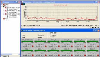
In this case, each phase is separated into 12 zones, one for the feeder section and 11 for each cable section between two joints. With CHARON, each phase temperature profile along the cable route and temperature drifts at critical points can be processed and displayed efficiently.
 |
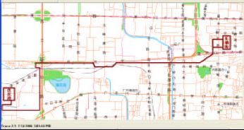 |
| CHARON screenshot showing temperature profile of one cable phase and its assigned zone display | CHARON Enhanced View screenshot of the cable route |
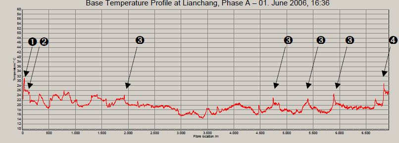
The screenshot of the temperature survey before initial operation (below) reveals the complexity of the cable route. The average temperature of the tunnel is about 20°C. Lowest temperatures of about 16°C are seen in the area of a railway crossing at an increased laying depth. Several peaks are caused by cable crossings of high and medium voltage cables (mark O).
The two peaks at the beginning and at the end (marks 0 and º) result from higher temperatures of the fiber optic feeder cables installed in cable ducts till the wall transition (mark A). Especially the temperature peak at mark º close to the edge of this installation at 7 km distance is precisely covered, as the spatial resolution setting applies for the entire sensor range. This is a unique feature of the OFDR measurement principle.
The installed DTS system enables the operator to monitor the cable conductor’s maximum operating temperature of 90°C in a narrow surrounding with a large number of other cables and cable crossings. It supports the real-time management of possible hotspots along the cable route even under overload conditions and thereby helps to avoid early breakdowns.